Practical Examples
The following examples will give you an insight into our daily routine – from examining the task to finding an individual customer solution.
-
Wastewater Stripper
Wastewater treatment using stripper columns. Following the client, the current system has reached its capacity limit concerning flow rate and thresholds
-
COD Process
The reactive conversion of process streams to Diesel in an oil refinery has been first analysed in the laboratory and on a pilot plant and then tested on industrial scale.
-
Tube Reactor
Cooled tube reactor for exothermic reaction. Catalyst deterioration above average due to the high thermal load.
Initial Situation
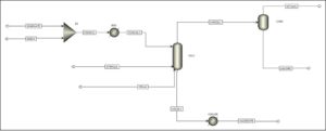
Wastewater treatment using stripper columns. The current system has reached its capacity limit concerning flow rate and thresholds.
The Task
Design a new column including an evaporator and a refeed system to increase the capacity by 30% taking into account the wastewater streams of additional plants.
Project Management
Modelling
- Adapting data of substances for the real system (chemical and physical properties).
- Conducting sensitivity analyses using different components in the column based on former laboratory and process data.
- Identifying the parameters that influence the performance of the system the most.
Insights
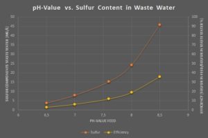
- pH-value of the induced wastewater shows significant impact on the threshold.
- Heavy fluctuations dependent on the chronological discharge of wastewater from different plants.
- Under ideal conditions (concerning pH-value) there are spare capacities in the existing system.
Design Proposal
- Expand the puffer tank in front of the column to equally distribute the feed.
- Install an acid metering to adjust the pH-value.
- Enlarge the column evaporator to allow for an increased capacity.
- The hydraulic system of the column is working on ideal terms even at an increased capacity of 30%.
- The refeed system (condenser, container, pump, valve) is suitable for an increased flow rate, if the pH-value is controlled.
Process Engineering Design
Customer Benefits
- Existing column can still be used including the refeed system!
- Improved process comprehension thanks to the sensitivity analysis!
- Reliable compliance with legal thresholds!
- Easier plant operation due to pH-value adjustment!
Initial Situation
Following laboratory and pilot plant analyses of an oil refinery, the reactive conversion of process streams to diesel shall be tested on industrial scale.
The task
- Implement the insights of the laboratory and pilot plant tests into an explicit simulation model.
- Optimise the product treatment and refeed of recycling streams.
- Provide a mass and energy balance for an industrial plant.
- Design the main equipment for an estimation of costs.
- Create a control concept for the plant.
Project Management
Modelling
Design a simulation model based on the insights of the laboratory tests. Adapt the data of the chemical and physical properties of substances to the test results. Conduct sensitivity analyses to optimise the product treatment and refeed of recycling streams. Create an adjusted simulation model based on the results of the sensitivity analyses.
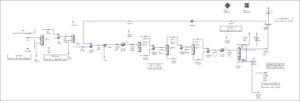
Process Engineering Design
Columns
- Calculate the required separating stages for the distilling columns.
- Choose the column components.
- Determine the column dimensions considering the hydraulic pressure.
Heat Exchanger
- Selection of evaporator, condensers, heater and cooler.
- Calculation of the required exchange area and the main dimensions.
Container
- Determine the vessel design taking into account the necessary retention time.
Pumps
- Set up the data sheets for all pumps necessary in the engineering process.
Control Concept – EI&C
- Design the concept to control the process including all control loops and EI&.
Customer Benefits
- Essential insights into potential improvements and costs of the industrial plant early on in the project.
- Facilitation of the Stop or Go decision.
- Accurate basis for further engineering.
Initial Situation
Cooled tube reactor for exothermic reaction. Catalyst deterioration above average due to the high thermal load. Decomposition components of the catalyst have been found in the product.
The Task
Identify the right amount of cooling water to avoid any catalyst deactivation due to the high thermal load.
Project Management
Modelling
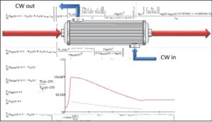
- Design a rigorous simulation model of the integral exchanger reactor to calculate the heat transmission.
- Modelling of the reaction kinetics to determine the energy balance.
- Combination of both models.
Insights
The required temperatures to thermally deactivate the catalyst couldn’t be reached in the model, not even using the current amounts of cooling water.
Following customer feedback we discovered that also the uncooled part of the heat exchanger (calotte at the inflow) was filled with the catalyst. Another modelling based on adjusted conditions showed a significant temperature peak in the uncooled part of the reactor.
Design Proposal
- Calotte at the inflow shouldn’t be filled with the catalyst.
- Installation of an additional reactor bed after the tube reactor discharge to increase the conversion.
- There is no additional cooling necessary due to the low discharge at the end of the reaction.
Process Engineering Design
New Equipment
- Additional reactor bed
Revision of the existing equipment
- Thermal load of the tube reactor
Customer Benefits
- Better understanding of the existing problems in the process.
- The considered solution to increase the cooling water flow wouldn’t have been successful. Unprofitable investment in a new cooling water pump would have been the consequence.
- Easy solution thanks to the tube extension with catalyst filling.